La CasaC - Software Design
Introduction
La CasaC is a comfortable, energy efficient, low maintenance and sustainable house. It is an ongoing project me and my wife started back in 2012. After three years of design and planning and two years of construction we moved in.
When I started planning La CasaC I had two options: use commercial products like home automation controllers, security lighting, burglar alarm, etc. and then spend my time trying to integrate proprietary protocols or use Open Source hardware and software to build/integrate everything from scratch. Having suffered the commercial/closed approach with my previous house I decided to try the latter.
Overall system design
Building the system from scratch was a significant challenge given the scale of the project. The “initial specs” based on the house blueprints and family expectations included:
- 40 Wall switches to turn lights on/off (i.e. over 45 Light channels to control 136 lamps!)
- 2 Garage doors and 2 doors with an electric lock
- 2 Mechanized awnings that had to follow the sun on summer to keep the living room cool
- 55 sensors (doors switches, PIR sensors, water flood, pool alarm)
- A weather station
- A solar water heater
- 7 indoor air conditioning units
- 2 bathroom heaters and 2 bathroom fans
- A kitchen range
- 8 smoke detectors/air quality sensors
- A four channel energy meter with an automatic transfer switch to a backup power generator
- A whole house PA system for TTS cues
- 2 RFID keypads for access control
- 4 433Mhz RF receivers
This list adds up to over 200 “things” that the house needs to operate. In order to cope with complexity, I distributed the “things” across seven controllers (Arduinos) which are in physical proximity to the sensors/actuators. This also helps reduce the need for cabling. Each of these Arduinos (called slaves) can operate independently and carry out logic that does not require global visibility or remote resources (i.e. not physically connected). For example: a wall switch rule can directly control a set of local lights.
The seven Arduino slaves are connected to an Arduino master using an RS485 network. The master node polls each slave 4 times per second and executes rules that spawn multiple slaves or that require global or contextual information like time, people presence, sun position, etc.
The master node is also the boundary between the “in wall” control system (aka domotics) and the building management system. The master Arduino node is connected to the house LAN and exposes simple/crude REST commands to the building management software.
The following picture provides an overview of the multiple layers that make up La CasaC

Starting from left to right
- Surrogate modules: Some of the sensors are themselves small controllers that do not interface directly to the house RS485 network and get exposed through a slave node (e.g. the weather station, the energy meter, the climate controllers, etc)
- Slave nodes
- Master node
- Building Management node: This node includes a couple of software layers. A REST proxy that adds abstraction to the Master node’s API and provides caching and access control (MTLS). An archiving process that converts the sensor data recorded by the master into CSV and stores it on the house NAS. An instance of OpenHab which provides building management services.
“In wall” hardware platform
All the Arduino based slave and master nodes are made using mostly off the shelve modules which are bolted onto a piece of plywood and wired all together. I refer to each piece of plywood as a “motherboard”. Although there are commonalities across the eight motherboards in La CasaC, each one is unique based on the functions it carries our for the house.
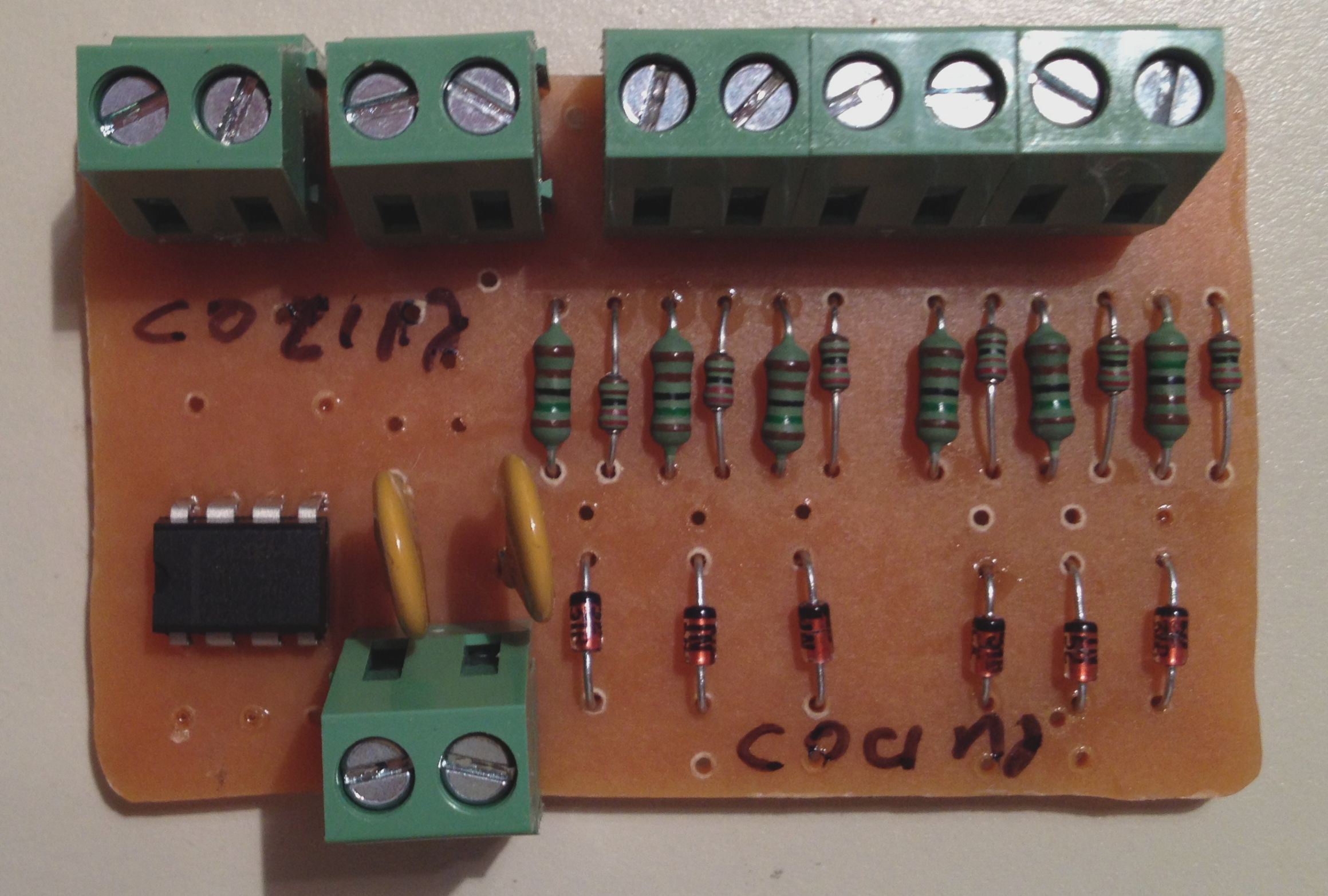
Sample motherboard

Here is a list of some of the modules a motherboard can include
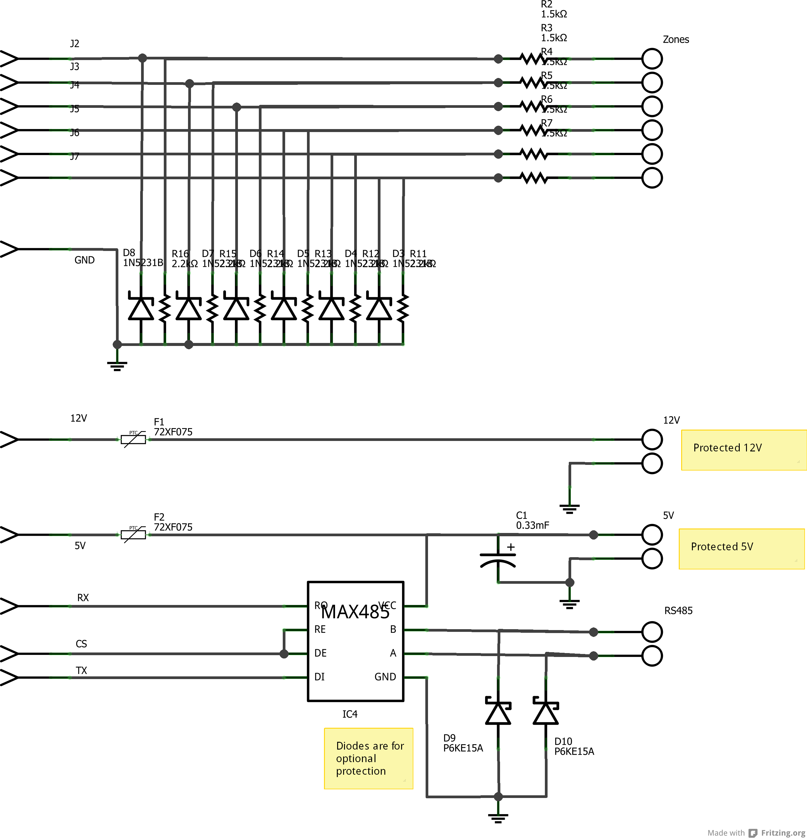
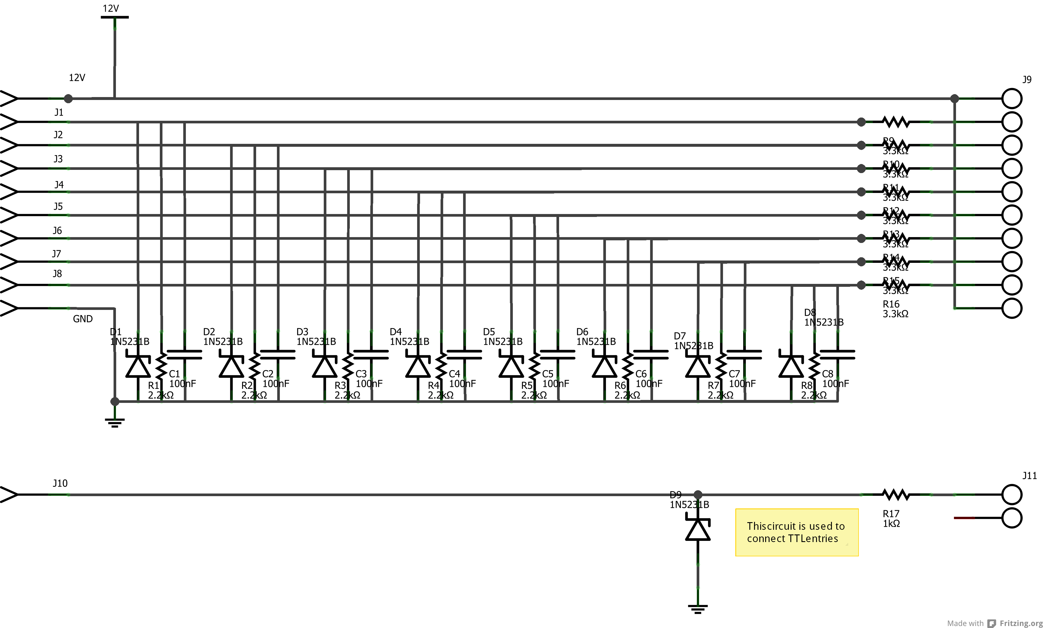
- Alarm loops interface & RS485 driver module ( schematics, assembled module)
- Relay modules. Mechanical relays are used to command high & low voltage actuators like doors strikes, water valves, awnings, electric water heater, pool water pump, etc.
- Weather station RS232 interface module ( reference on how to interface a Lacrosse WS-2317U weather station)
- Water level & temperature interface module ( reverse engineering notes)
- Light sensor module
- Flood sensor module
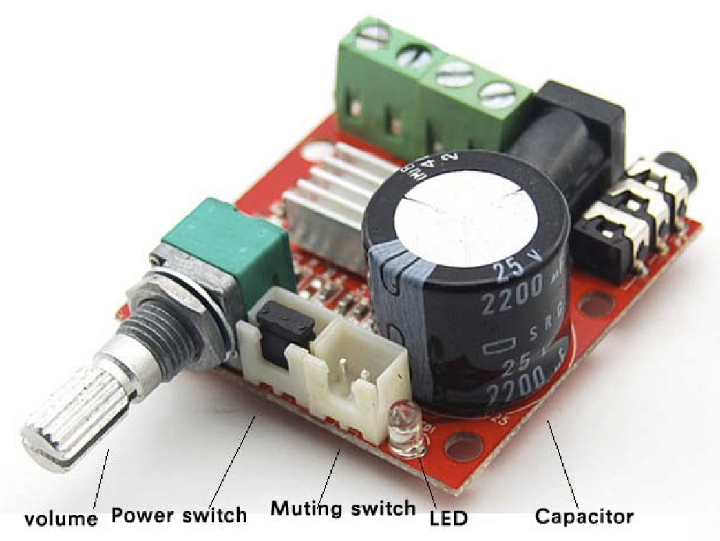
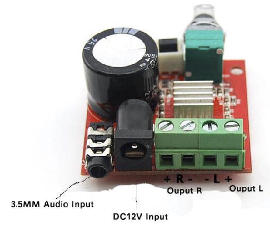
- Digitally controlled PA audio amp module ( Pic1, Pic2, based on the PAM8610)
- RFID & Keypad module (Wiegand26 based, libraries/CardReader/CardReader.cpp:20)
- MP3 player to play pre-recorded TTS voice cues ( WTV020-SD reference page)
- Battery backed up real time clock (based on DS1307)
- Ethernet shield ( W5100 reference)
The following modules are placed externally to the motherboard to keep the mains voltage separated from the low voltage circuitry
- Power supply
- Wall switches module ( schematics)
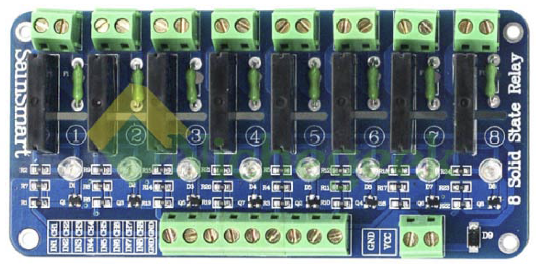
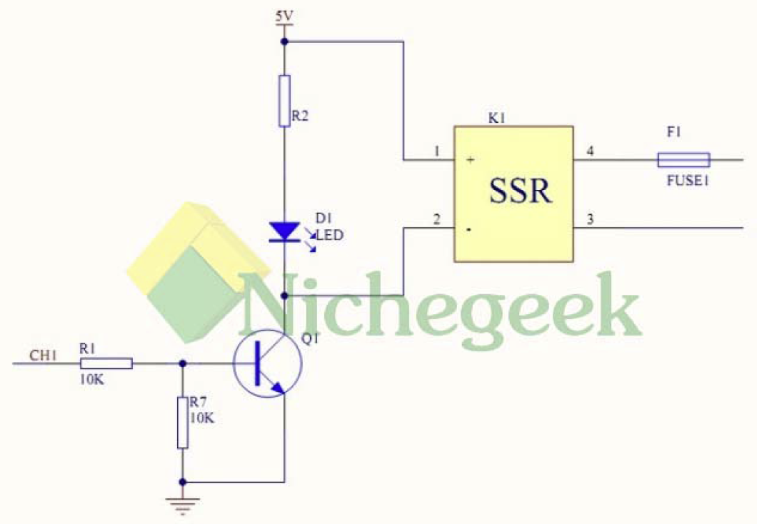
- 5V Solid State Relay Shield ( Pic1, Pic2)
Here is an example of a fully assembled mother board installed on “the wall” with the external modules housed on a different case

This is the same motherboard before being installed

“In wall” software design
The in wall software follows loosely a dependency injection pattern (solved at compile time). All slaves share the same code and their functional differences are injected through slave specific functions. The master has a different codebase but its extensibility is also done through dependency injection. In theory the codebase could be reused on a different house without having to change the bulk of the code (i.e. over 40K lines of C/C++).
The core home automation logic is expressed as simple if-then rules on an Excel sheet. These rules are compiled into C code and are injected as dependencies to the slaves and the master node. The rule compiler (a.k.a. ResourcePreprocesor) can break complex rules across multiple slaves and the master. Every wall switch, sensor, light, etc. has an identifier which is referenced on rules (see IO access constants).
At runtime the master node polls all slaves for updates every 250ms (i.e. 4 times per second). Slaves reply with a portion of their sensor memory map that includes digital I/O and alarm loops (see Memory maps & zone masks). Alternatively, slaves may reply with an event for the master. Every 30 seconds each slave is also asked for its full memory map (called extended polling). This brings into the master other sensors like weather station, water heather data, light sensors, etc.
This is a list of the key injection points for a slave node:
- void initTasks(void) Called during node initialization to setup any node specific classes
- int loadEECfg(void) Called during node initialization to load local configuration parameters from the EEPROM
- void initSensors(void) Called during node initialization setup any sensor that is not manage by SensorAcq. Only wall switches & alarm loops are automatically acquired by SensorAcq
- void acquireSensor(byte sensorNo) Called to acquire sensors not managed by SensorAcq like flood sensor, light sensor, weather station, etc.
- void dispatchSensorEvents(byte signal, byte value) Called when there is a state change on a local sensor to implement a local automatism. This function also includes LIST_OF_ACTIONS which is a set of switch conditions that are generated by the rule compiler
- void p2loop() Called regularly after all the critical tasks have been performed
- void sendEventsToMaster() Called when the master node polls the slave to collect any events that need to be propagated to the master
The master node performs slave’s functionalities for all its locally attached sensors. Therefore, all the previous functions apply on the master plus the following:
- bool loadSDCfg(void) Called during initialization to load master specific configuration data from the SD card
- void warmingUpCompleted(void) Called after the master has been running for a bootstrap period to continue enabling functionality that has dependencies on 1st tier services
- void extendedPollCallBack(byte node) Called after an extended poll is performed on a slave to trigger additional processing
- bool discreteHouseEventDispatcher(byte evType, byte size, byte *buff, unsigned char nodeEntry) Called when the master receives an event from an slave to do additional processing (e.g. RFID/keypad access, slave threw an exception)
- The master node uses a limited eventing pattern to process changes to sensors. Event handlers (called Dispatchers) can subscribe to the event stream.
- void houseAutomationDispatcher(unsigned int event, SensorValue value, byte zoneNo) This dispatcher handles the rules that span across nodes using the LIST_OF_GLOBAL_ACTIONS code generated by the rule compiler